

Saltwater Intrusion
Saltwater intrusion is an increasing concern for drinking water systems in coastal regions. Increasing chloride can affect drinking water quality, infrastructure corrosion, and supply reliability.
Before we dive into the jargon, let’s define a few important terms that will be used in this blog:
- Aquifers: An underground layer of water-bearing permeable rock, or unconsolidated materials (gravel, sand, or silt) from which groundwater can be extracted using a water well
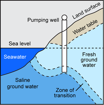
- Zone of Transition: Rather than a sharp boundary, a dynamic mixing area exists where fresh and saline groundwater meets. (Figure 1)
- Chloride concentration: Amount of chloride ions dissolved in water measured in mg/L. It serves as an indicator for measuring the salinity in drinking water supplies. The EPA’s secondary (non-enforceable) limit for chloride concentration in drinking water is 250 mg/L. Typical values of developed watersheds are between 10-50mg/L.
In coastal aquifers, less dense fresh groundwater floats above saline groundwater, separated by a transition zone. Intrusion can occur when extraction of the fresh water lowers the water table and creates a pressure drop that draws the underlying saline water upward toward the well. Saltwater upconing pulls this saline zone directly into the well, contaminating the fresh water supply (Figure 1). Monitoring in coastal areas of southern Delaware shows elevated chloride levels where human activities alter groundwater levels (pumping, ditching). The elevated chloride is happening in conjunction with environmental factors such as sea-level rise and drought.
Monitoring
Monitoring plans and installing wells strategically to measure water levels can provide data to determine where the water table is and if it is being lowered by pumping. Water quality sampling lab testing for chloride, or sodium, or specific conductivity, and total dissolved solids in the lab can provide a good indication of saltwater intrusion. Take samples in January, May, July and September to isolate extreme hydrological shifts, seasonal weather patterns, and land-use activities that cause salinity and dissolved minerals to fluctuate in an aquifer.
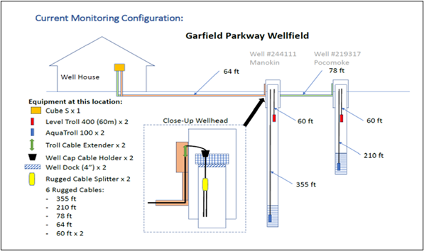
An example monitoring strategy is placing a monitoring well between the pumping center and saltwater body as shown in Figure 2. While monitoring, it is important to look at long term data and not take a single sample as water quality value. Small systems with low capacity should, at a minimum, collect water samples from the production wells and test the chloride levels and plot data to see if there are long term trends.
While monitoring thresholds offer useful guidance, a system’s actual response depends on what the data reveals. Therefore, continuous data collection and long-term trend analysis are essential.
Table 1: Chloride concentrations and considerations
| Threshold | Value | Meaning |
| Early Warning Level | 50–100 mg/L | Indicates potential migration |
| Action Threshold | 150-200 mg/L | May require operational response |
| EPA Secondary Standard | 250 mg/L | Taste/aesthetic (not enforced) |
| Critical Level | >250 mg/L | Likely user complaints + system risk |
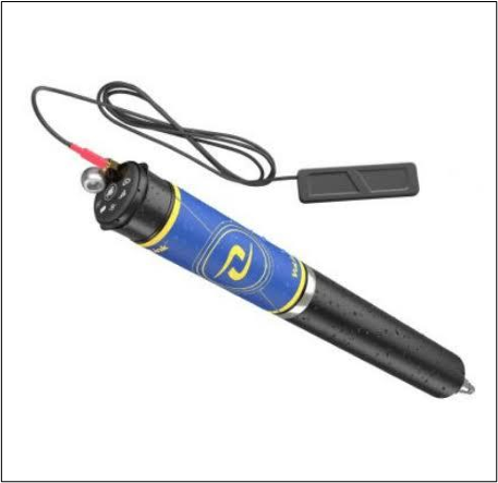
Monitoring in a well can be done with telemetry equipment attached to transducers which can measure a range of data constantly. These tools like the one shown in Figure 3 can measure barometric pressure, depth to water level, specific conductivity, pressure, temperature, total dissolved solids, resistivity, salinity, density, and actual conductivity and only require one cable and one transducer.
Actions
Water systems can take several proactive measures to manage and mitigate saltwater intrusion. For example, reducing or changing pumping schedules, either by reducing the pump rate of a particular well depending on how long that well pumps and/or rotating wells so that you can give a chance for different wells to rest.
Blending is another option if your infrastructure permits combining higher- and lower-value well water. Moving well locations further inland or tapping into a different aquifer may be an option to reduce salinity risks, as chloride concentrations often vary across different aquifers in the same location. Additionally, establishing an interconnection with a neighboring public water supply system can serve as a viable alternative.
Note: The EFCN does not endorse the use of any particular product, and any products are referenced for informational purposes.