
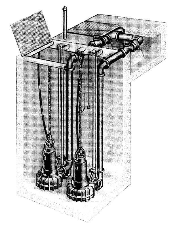
Wet Well – Submersibles. Basic Wastewater Collection Systems. Minnesota Pollution Control Agency. (1995) https://www.pca.state.mn.us/sites/default/files/wq-wwtp8-26.pdf
Lift stations are installed at low points in the collection system where continued gravity flow is not possible or practical. A high level of reliability is required for lift stations because failures can result in sanitary sewer overflows of raw wastewater leading to potential compliance problems while threatening public health and the environment. In order to ensure uninterrupted function, several components of the lift station must work properly. In this post, we will review the main components of lift stations and identify ways that operators can inspect, assess, and maintain them.
Level Controls
The float level control system is the most widely used and most basic control system used in lift stations. It normally consists of four or more float switches attached to cables which are installed in the wet well. The float switches turn pumps on sequentially as the level of wastewater in the wet well increases and turns them off when the wet well has been drawn down after pumping. Also, the upper float will provide a high-level alarm that alerts operators that the pumps are not functioning properly or are unable to keep up with the flowrate coming into the lift station. Common problems with these types of systems include the floats or wires becoming entangled or coated with grease that prevents them from actuating. To ensure proper function, operators should inspect and clean the floats and cables at least quarterly, taking note of any excessive floating grease or other material in the wet well that may be accumulating. In addition, operators can test each float by using a float hook tool attached to a long pole that allows each float to be lifted manually. Click here for more information from the EPA.
Pumps and Motors
Important aspects to monitor for motors are the number of hours of run time, the number of run cycles that occur each day, and the amperage draw of each motor. Most lift stations in collection systems have at least two pumps which alternate as the lead and lag pump. The lead pump is the first pump to come on, and the lag pump switches on if the flow is too high for just one pump to keep up. Operators record the hours of run time to ensure that each pump is operating roughly the same amount of time and to identify when key maintenance activities should occur. Increased monthly run time for just one pump may indicate a problem with the pump or lack of proper alternation. Alternatively, an increase in run time for both pumps may indicate increased flow due to a problem with inflow-infiltration or recirculation due to a failed check valve. Some lift stations may also have cycle counters which indicate the number of pump starts; this can provide valuable information for operators that allows them to compare current data to normal running conditions.
Amperage draw while the pump is running can provide essential information that can reveal problems; particularly, increased amperage draw can indicate that the motor is working harder to overcome added resistance, or that there is an electrical problem. Excessive amp draw could indicate a bad bearing or even obstruction in the piping. Three phase electrical motors have three 220 V or 480 V leads that must be checked for amperage imbalance issues. To do this, the amperage draw of each leg is compared to the average amperage draw for the pump motor. If the amperage of any leg exceeds the average by 5% or more, there may be an amperage imbalance that needs to be corrected. Often, amperage imbalances can be corrected by simply rotating the leads that connect to the motor; however, an amperage imbalance can also indicate a problem with the motor or the electrical distribution system that may require analysis by a qualified electrician.
Measuring the output flowrate and the efficiency of the pumping operation can also provide insight into when pump impellers may need to be adjusted or replaced. Lift stations create harsh, corrosive conditions in which pumps must operate which can lead to impeller wear. Excessive clearance between the impeller and pump casing reduces the efficiency of pumps by allowing recirculation to occur. It is important to minimize the detention time of wastewater in lift station wet wells in order to prevent septicity, prevent deposits, and minimize objectionable odors. Therefore, pumps should be operating at full design capacity. However, there are times when the wastewater flow may be less than design; at such times the lift station needs to be monitored frequently. Sometimes lift station pumps are equipped with flow meters that allow operators to directly read the flowrate for each pump; however, flowrates can also be determined with a drawdown test based on the time required for each pump to empty the known volume of the wet well. Pumping rates should be compared over time in order to identify any pump problems.
Pumps can become clogged, blocked, or tangled with waste, grease, and rags. Some lift stations include bar screens or cages around the pumps to prevent this from occurring. An increasingly more common solution involves the use of grinder pumps which cut wastewater solids into smaller pieces that will more easily pass through the pumps. Some manufacturers are producing self-cleaning pumps which are intended to prevent pump impellers from being entangled by rags. Still, frequent checks and inspections by operators can not be replaced as a way to ensure that pumps are clear of debris and operating properly.
Valves and piping
Lift stations are equipped with check valves to prevent pumped wastewater from flowing backwards through the pump and back into the wet well; this means the same liquids must be pumped again leading to increased pump run time and wear. Occasionally, check valves can become stuck partially open due to grease, waste, and soup accumulation. When this happens, operators will likely notice a significant increase in motor run time. The best way to prevent this from happening is to thoroughly clean the lift station periodically. Downstream piping can also become clogged, or piping can develop leaks due to corrosion or external damage. To detect these downstream problems, operators should install a pressure gauge on the force main leaving the lift station. A significant increase in pressure over time can indicate a clogged pipe or valve, while a decrease in pressure can indicate a break or leak.
In Summary
While lift stations are complex systems in which several components operate automatically, operators can improve reliability by tracking run times of pumps, monitoring downstream pressure, keeping floats and check valves clean, monitoring pump flow rates and efficiency, and frequent visual checks of the site. Paying attention to these basic system operation and maintenance tasks can help to maintain reliability, compliance, and public health.
References and Additional Resources
- USEPA (2000). Collection Systems Technology Fact Sheet: Sewers, Lift Station. EPA 832-F-00-073. https://www3.epa.gov/npdes/pubs/sewers-lift_station.pdf
- Water Environment Federation (2019). Sanitary Sewer Systems: Lift Stations and Data Management Fact Sheet. https://www.wef.org/globalassets/assets-wef/direct-download-library/public/03—resources/wsec-2019-fs-013—csc-mrrdc—lift-stations-and-data-management—final.pdf
- Minnesota Pollution Control Agency. (1995). Basic Wastewater Collection System. https://www.pca.state.mn.us/sites/default/files/wq-wwtp8-26.pdf
- Schwindamann, C. (2017). The Kansas Lifeline. Basics of Lift Station Maintenance. https://krwa.net/portals/krwa/lifeline/1703/BasicsofLiftStationMaintenance.pdf
- Phoenix Pumps (n.d.). Standard Operating Guideline. Lift Station Inspection. https://www.phoenixpumps.com/pdf/Lift_Station_Maintenance_Guidelines.pdf